
|
|
|||||||||||||||
Week 1: |
|||||||||||||||
|
Commencing 14th September 2004 |
|||||||||||||||
|
14-09-04 |
I was given an assignment to design and build and electronic device, and then do a presentation about it. I chose to make an electronic people counter to count the number of people that enter a room. The device must have a digital display and two beams that must be broken in order for the counter to work. A timescale was set stating the dates that specific stages must be complete, these were as follows:
|
||||||||||||||
|
18-09-04 |
I have posted a question to an electronics forum on the internet, to ask if anyone had ideas on how to make the counter work when beam 1 then beam 2 is broken, and not the other way round. I have had suggestions of writing a simple program for a PIC, or logic gates. |
||||||||||||||

|
|
|||
Week 2: |
|||
|
Commencing 21st September 2004 |
|||
|
21-09-04 |
Research ideas on the internet of possible counter systems. I have found a 4½ Digit counter that will count up to 19999. There are also complete counters with the LCD display included, with a maximum count of 99999. |
||
|
25-09-04 |
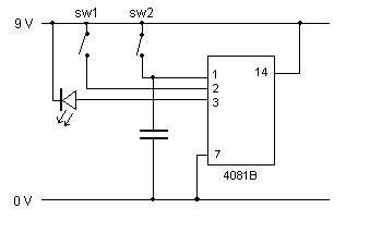
Designed a trial section of the circuit and purchased components to make it. I am experimenting using a capacitor to create a time delay. When beam 1 is broken the capacitor will charge up. When beam 2 is broken the charge from the capacitor, plus the power from beam 2, will make both inputs on the AND gate go high, giving an output to the LED. This will not work when the person walks through the beams the other way, as input 2 will not be high when beam 1 is broken. (The LED is just used for reference, and pin 3 will be connected to the counter input in the finished product.) |
||
|
26-09-04 |
Made the circuit as in the diagram. It didn’t work as I expected, the LED was on whether the switches were closed or not.
|
||
|
27-09-04 |
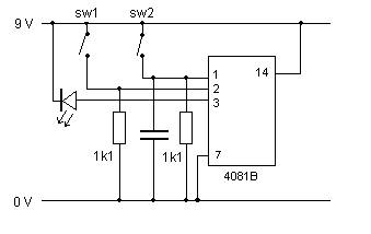
I discussed my findings with the technicians at work and concluded that the inputs were floating. To cure this I decided to add resistors to the circuit.
|
||
|
|
|||
Week 3: |
|||
|
Commencing 28th September 2004 |
|||
|
28-09-04 |
Tried different value capacitors, to get a suitable time delay. This resulted in using two 470µF in parallel. Researched on the internet for infrared circuits. The aim is to find a suitable way of connecting the IR beams to the counter |
||
|
30-09-04 |
Re-designed the test circuit of 27-09-04, to enable the time between beam 1 and beam 2 to be increased. I changed one of the resistors from 1k1 to 9k1, and removed one of the capacitors. This has created a time delay of 3-4seconds. |
||
|
|
|||
Week 4: |
|||
|
Commencing 5th October 2004 |
|||
|
5-10-04 |
Researched existing people counting products available. There is a wide variety available, including those that can be connected to a PC to download the data, or have heat sensing technology enabling them to do a head count. |
||
|
6-10-04 |
Purchased and assembled an Infrared Beam Breaker kit, to understand how the beam breaker circuit would work. I found that the transmitter did not send a signal in a direct straight line, but could be detected by up to 30cm either side at full range (4metres). I modified the circuit by putting a tube over the transmitter LED’s, enabling two transmitter/ receivers to be placed closer together. |
||
|
|
|||
|
|
|||||||||||||
Week 5: |
|||||||||||||
|
Commencing 12th October 2004 |
|||||||||||||
|
12-10-04 |
I created a parts list for infra red receiver section of the circuit. . I then designed the board layout. |
||||||||||||
|
|||||||||||||
|
|
|||
Week 6: |
|||
|
Commencing 19th October 2004 |
|||
|
19-10-04 |
I found the parts required for the receiver circuit in the college spares store. I then laid out the circuit on the veroboard as shown in my diagram, and soldered in the parts. I ordered an LCD display and a bi-colour (red and green) backlight from Farnell. |
||
|
(diagram/ photo) |
|||
|
|
|||||||||||||
Week 7: |
|||||||||||||
|
Commencing 2nd November 2004 |
|||||||||||||
|
2-11-04 |
I created a parts list for infra red transmitter section of the circuit. I then designed the veroboard layout. |
||||||||||||
|
|||||||||||||
|
|
|||
Week 8: |
|||
|
Commencing 9th November 2004 |
|||
|
9-11-04 |
No project work. |
||
|
|
|||
Week 9: |
|||
|
Commencing 16th November 2004 |
|||
|
16-11-04 |
I created one of the receiver circuits for the infra red beam detector, on Veroboard. I sourced the Veroboard and PP3 battery connectors from work and the capacitors, resistors, transistors, LED and links from college. The circuit didn’t work correctly on first attempt. The LED was permanently lit, suggesting that the beam was broken, even when it wasn’t. I will start to fault find the circuit next week. |
||
|
|
|||
Week 10: |
|||
|
Commencing 22nd November 2004 |
|||
|
22-11-04 |
The problem with the receiver part of the second beam was that the LED is permanently lit. The LED should only light when the beam is broken. As there are two circuits the same (one for each beam) with one working correctly, I was able to make a comparison of the voltages at certain points. Starting from the input, I was able to use the split-half technique. |
||
|
Test Applied |
Results |
Conclusions |
|
|
DC voltage check supply rails |
Expected 9V Found 9V |
Fault lies between output and input |
|
|
DC voltage check junction R8 and C3 |
Expect 7.05V Found 7.05V |
Fault lies between junction R8 and C3 and input |
|
|
DC voltage check junction C2 and R5 |
|||
|
DC voltage check junction R3, R1 and T1 |
|||
|
|
|||
Week 11: |
|||
|
Commencing 30th November 2004 |
|||
|
30-11-04 |
|||
|
|
|||
Week 12: |
|||
|
Commencing 7th December 2004 |
|||
|
7-11-04 |
Work training course. |
||
|
|
|||
Week 13: |
|||
|
Commencing 14th December 2004 |
|||
|
11-01-05 |
LCD display and backlight arrived. The backlight is divided up into several segments. There are six red LEDs on one side and six green on the other (one pair for each segment of the LCD display.) I tested the backlight to check that all of the LEDs were working correctly, which they were. |
||